Pilot Study for Considering Subthalamic Nucleus Anatomy during Stimulation Using Directional Leads
Article information
Abstract
Objective
Directional leads are used for deep brain stimulation (DBS). Two of the four contacts of the leads are divided into three parts, enabling controlled stimulation in a circumferential direction. The direction of adverse effects evoked by DBS in the subthalamic nucleus (STN) and stimulation strategies using directional leads were evaluated.
Methods
Directional leads were implanted into the bilateral STN of six parkinsonian patients (1 man, 5 women; mean age 66.2 years). The contact centers were located within the upper border of the STN, and the locations were identified electrically using microrecordings. Adverse effects were evaluated with electrical stimulation (30 μs, 130 Hz, limit 11 mA) using the directional part of each lead after surgery, and the final stimulation direction was investigated. Unified Parkinson’s disease rating scale (UPDRS) scores were evaluated before and after DBS.
Results
Fifty-six motor and four sensory symptoms were evoked by stimulation; no adverse effect was evoked in 14 contacts. Motor and sensory symptoms were evoked by stimulation in the anterolateral direction and medial to posterolateral direction, respectively. Stimulation in the posteromedial direction produced adverse effects less frequently. The most frequently used contacts were located above the STN (63%), followed by the upper part of the STN (32%). The mean UPDRS part III and dyskinesia scores decreased after DBS from 30.2 ± 11.7 to 7.2 ± 2.9 and 3.3 ± 2.4 to 0.5 ± 0.8, respectively.
Conclusion
The incidence of adverse effects was low for the posteromedial stimulation of the STN. Placing the directional part of the lead above the STN may facilitate the control of dyskinesia.
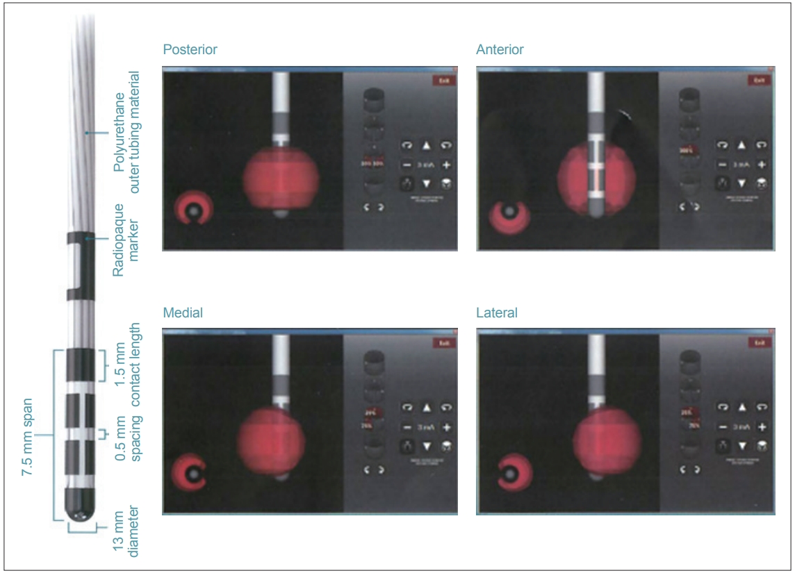
Deep brain stimulation (DBS) is an established method to treat individuals with advanced Parkinson’s disease (PD) [1,2]. The present study investigated DBS using a four-contact directional lead that has recently been introduced to the market (Vercise Cartesia, Boston Scientific, Marlboro, MA, USA) (Figure 1) [3]. Unlike conventional cylindrical leads, this novel lead has two smaller middle electrodes that is segmented horizontally into three contacts, which can be stimulated independently by multiple independent current control (MICC) technology (Boston Scientific). This obviates adverse effects by controlling stimulation in a circumferential direction away from structures associated with adverse effects. However, programming requires a conscientious awareness of the local anatomy surrounding the stimulation target(s), especially in the axial plane. Currently, though, no programming manuals for directional stimulation exist. In the present study, we investigated direction-evoked adverse effects using the directional part of the lead, and we discuss a treatment strategy for subthalamic nucleus (STN)-targeted DBS for PD using this lead.

Directional lead. The second and third contacts were divided into three parts. The strength and percentage stimulation of each contact can be independently controlled (Copyright©Boston Scientific, USA).
MATERIALS & METHODS
Six patients with advanced stage PD [1 man, 5 women; mean age 66.2 years (range, 49–74 years); mean disease duration 9.3 years (range, 5–15 years)] implanted with directional leads and an implantable pulse generator (Vercise PC, Boston Scientific) targeted to the STN were enrolled in the present study (Table 1).
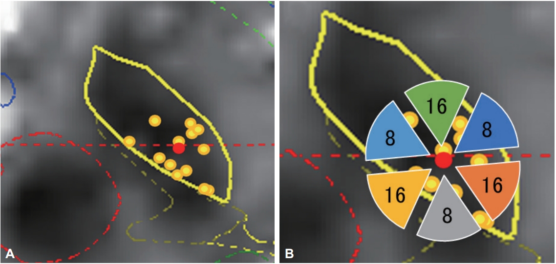
The targets were determined directly by magnetic resonance imaging (MRI). The burr hole site was located near the coronary suture. The surgery was performed using the Leksell stereotactic frame (Elekta, Stockholm, Sweden). The electrodes were inserted in the bilateral STN using the Ben Gun approach, and the optimal trajectory and depth were determined using microrecordings. The leads were located so that the centers of the two middle, radially segmented electrodes were located at the dorsal borders of the bilateral STN (Figure 2). After stimulation trials, an implantable pulse generator was subcutaneously inserted and connected to the leads. Postoperative lead positions were identified by fusing postoperative three-dimensional computed tomography images with the preoperative MRI. The position was plotted onto the STN axial images of the unilateral side (Figure 3A). The direction of the contact was confirmed using radiopaque markers detected with postoperative X-ray. Because the direction of the contacts varied widely, the contact direction was divided into six parts in increments of 60° (Table 2, Figure 3B).

Distribution of stimulated contacts in the vertical direction. The midpoint of contacts was located in the upper border of the subthalamic nucleus, as detected by microelectrode recordings. The percentage (%) of the first (bottom) to fourth (top) contacts was calculated as follows: (summation of % of each contact stimulation of all leads)/12 (total lead number). The percentage of the second and the third (directional part) contacts was calculated as follows: (summation of % of three contacts at the same level of all leads)/12.

Location of implanted leads and number of contacts. A: The location of implanted leads was plotted from postoperative computed tomography images superimposed on preoperative magnetic resonance images on the unilateral STN. B: The number of contacts located in each direction. All leads were inserted into the STN. The same template on the left and right was described as unified, so that the right side is outward. The red dot represents the center of all leads. The direction of contacts was placed in sextiles. STN: subthalamic nucleus.
One week postoperatively, a maximum current of 11 mA (30 μs, 130 Hz) was used to determine the threshold for adverse effects. A 30-μs stimulation was adopted based on previous results showing that a wider therapeutic window of amplitude could be obtained by 30 μs than by 60 μs stimulation [4-6]. The presence or absence, type, and direction of adverse effects were investigated. To determine the final stimulation conditions, the stimulation set was adjusted mainly at the site where the maximum of motor symptom improvements were obtained without adverse effects. To determine the final stimulation conditions, the pre- and postoperative unified Parkinson’s disease rating scale (UPDRS) part III and IV scores, the dyskinesia part of the IV scores, and the levodopa equivalent daily doses (LEDD) were evaluated 1 year after starting the DBS (Table 1).
This study was approved by the Ethics Committee of the Kanazawa Neurosurgical Hospital (Nonoichi, Ishikawa, Japan, ID 29-07). Informed consent was obtained from all patients.
RESULTS
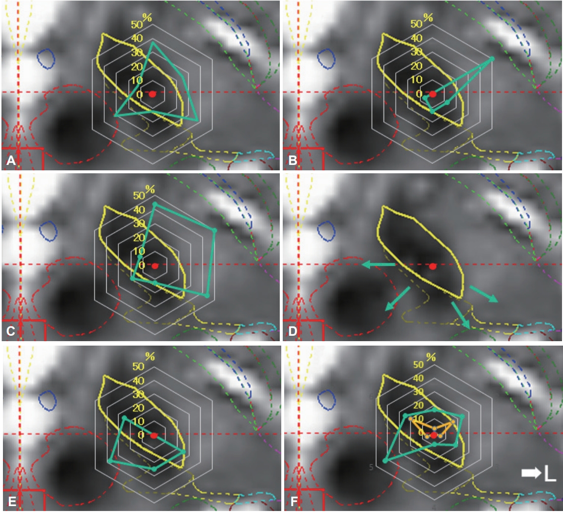
The actual positions of the inserted leads are shown in Figure 3A. All leads were inserted in the STN. A plot was made to indicate the center of the lead insertion (red circle in Figure 3A). Six directional leads for the six PD patients were bilaterally stimulated (72 segmented contacts in total), and the rate of occurrence of adverse effects was calculated. Figure 3B shows the direction of the contacts placed in sextiles. The number and rate of adverse effects evoked by stimulation in each contact are summarized in Table 2. The direction of the induced motor symptoms (A, hand motor contraction; B, foot motor contraction; C, face motor contraction/dysarthria), sensory symptoms (D, hand numbness), and the absence of adverse effects are shown in Figure 4. Radar charts representing the frequency of adverse effects are presented in Figure 4A-C, E. The frequencies of adverse effects reported in the charts were calculated as (number of adverse effects/number of contacts in each angle) × 100 and are depicted by dots. Motor symptoms were frequently observed in the anterolateral direction (Figure 4A-C). Hand numbness occurred in only four cases and was observed from the medial to posterolateral direction (Figure 4D). The absence of adverse effects was mainly observed in the posteromedial direction (Figure 4E). The final stimulation direction was divided into deeper contact (second contact from the tip of the lead) and upper contact (third contact from the tip), as shown in Figure 4F. All cases involved monopolar stimuli. The stimulation direction was contained within the STN and its posteromedial side. Viewed in the longitudinal direction, the percentage of used contact frequencies from highest to the lowest were the 3rd, 2nd, and 4th from the tip, but we did not use the 1st tip (Figure 2). The mean UPDRS part III (off-period) and part IV scores improved by 23.0 ± 12.3 (p = 0.03) and 5.2 ± 4.6 (p = 0.100), respectively, while the dyskinesia score decreased by 2.8 ± 2.3 (p = 0.100) (Table 1). The LEDD decreased by 180.5 ± 173.1 mg (p = 0.100) (Table 1).

Direction of adverse effects and distribution of stimulated contacts. Charts showing the direction of adverse effect incidence in each contact (A-D), direction of no adverse effect (E), and distributions of final stimulated contacts (F). The percentage values described in the radar charts were calculated as described in Table 2. Motor symptoms were induced by stimulation in the anterolateral direction (direction to posterior limb of internal capsule) (A, motor contraction of upper limb; B, motor contraction of lower limb; C, motor contraction of face and dysarthria). Sensory symptoms were induced by stimulation in the posteromedial direction (direction to medial lemniscus and ventral caudal nucleus of the thalamus; D). The percentage in which no adverse effects were induced was high in the posteromedial direction (direction to zona incerta or prelemniscal radiations; E). The final stimulation directions were determined by the clinical effects and adverse effects (F). The plots are divided into deeper contact (yellow color) and upper contact (green).
DISCUSSION
In this study, we investigated the correlation between the direction of stimulation and adverse effects of DBS. Traditionally, the direction in which adverse effects appear is determined by analyzing the results of stimulation when the lead or microelectrode deviates from the target due to individual anatomical variations. With the development of directional leads, we obtained the means to check the direction of adverse effects by changing the direction of stimulation in the same patient. Our results provide important information on the use of directional leads.
A higher frequency of motor symptoms appeared in the upper and lower extremities, as well as in the face/voice, and was higher in the anterolateral direction. This direction is consistent with the direction of the internal capsule. There were no differences in direction among upper/lower extremities and facial/oral motor symptoms; however, the frequency of lower extremity symptoms was significantly lower. Because the pyramidal tract in the posterior limb exhibits somatotopy in the order of face, upper limb, and lower limb from the front [7,8], distant fibers from the STN and lower limb are wider than those of the upper limb and face. The frequency of sensory symptoms was significantly lower (only four stimulations induced symptoms), and all sensory symptoms involved hand numbness. The direction was from the medial to the posterolateral side, which is consistent with the direction towards the medial lemniscus and ventral caudal nucleus of the thalamus. The reason for the fewer sensory symptoms could be that the sensory areas were not stimulated directly because the zona incerta (Zi) is located between these structures and the STN. Stimulation in the posterolateral direction infrequently induced adverse effects. This direction is consistent with the Zi or prelemniscal radiation (Raprl). Plaha et al. [9] reported that stimulation of the STN in the posteromedial direction induces hypotonic speech and balance disturbances because fibers from the cerebellum pass through that area; however, such adverse effects were not observed in our subjects.
In the finalized distribution of the stimulation contacts, the posteromedial side was stimulated by the upper contacts. The Zi and Raprl are located on the medial side of the STN. The region is a known target for DBS and a reported target for PD treatment [9,10]. These structures involve the dentate-thalamic tract and transmit tremor signals [11]. Thus, medial stimulation from the STN should induce fewer adverse effects, and favorable stimulation effects should be expected. Considering the longitudinal direction, most stimulations were located in the dorsal STN and upper contacts. This is consistent with previous studies, which identified the dorsal STN and the area above the STN (including the Zi and Forel H2) as the optimal stimulation points [12-14]. In particular, stimulation in the area above the STN suppresses dyskinesia through stimulation of the Forel H2 fiber from the internal globus pallidus to the thalamus (pallido-thalamic tract; lenticular fasciculus) [15-17]. Furthermore, our previous study showed that the leads pass through the anterior part of the ventral oral nucleus of the thalamus (Voa) when they are placed in more posterior and medial trajectories [14]. As we placed the leads in this way in this study, the upper-most contacts were located in the Voa. A previous study investigating coagulation in the Voa nucleus showed that rigidity, dystonia, and dyskinesia improved [18]. We found that upper contact (in the Voa nucleus) stimulation suppresses dyskinesia; however, gait was aggravated. We controlled gait and dyskinesia by vertical steering. More specifically, when dyskinesia appeared, we moved the stimulation point slightly upward, towards the upper contacts, and when patients experienced gait problems, such as freezing, we moved the stimulation point slightly downward towards the tip of the electrode, which may have resulted in satisfactory gait and dyskinesia control.
In conclusion, we believe that placement of the midpoint of electrodes in the upper border of the STN and fine vertical steering using MICC technology could be beneficial for dyskinesia suppression and gait control. Understanding the structures surrounding the STN is important for lead placement and for designing stimulation strategies using directional leads. A limitation of this study was that it was not possible to blind the test for doctors and patients regarding the stimulation. Since the sample size was rather small in this study, further investigation is warranted to confirm our results.
Notes
Conflicts of Interest
The authors have no financial conflicts of interest.


